
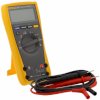


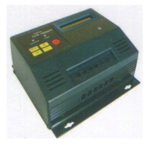

Mô tả sản phẩm: Đồng hồ để bàn Keithley 2750 Multimeter Data Acquisition Switch System
Tổng quan thiết bị:
Integra Series systems (2700, 2701, 2750) combine precision measurement, switching, and control in a single, tightly integrated enclosure for either rack-mounted or benchtop applications. These cost-effective, high performance test platforms offer affordable alternatives to separate DMMs and switch systems, dataloggers/recorders, plug-in card data acquisition equipment, and VXI/PXI systems. The Integra Series plug-in switching and control modules offer unmatched flexibility and testing efficiency for a wide range of industries and applications. System builders can create test solutions with a combination of channel count, cost per channel, and system performance unmatched by any other single-box measurement system. The input modules provide the flexibility to vary the channel count from 20 to 200 (2-pole), apply a stimulus to the device under test, route signals, control system components, and make precision measurements with up to 14 functions. Robust digital I/O capabilities can be used for triggering, handshaking with other automation equipment, and alarm limit outputs. Scan rates of up to 500 channels/second (up to 3500 readings/second on a single channel) will increase test productivity.
Fast Setup and Operation
The Integra systems are fully integrated, off-the-shelf measurement and control systems. Their DMM- like interfaces make it easy for users to collect data and/or perform troubleshooting within minutes of installation and startup. Once sensor or DUT leads are hooked to the instrument’s input, use the front panel controls to select the measurement function, range, filtering, scaling, trigger source, scanning sequence, alarms, and more. The free ExceLINX-1A software makes it easy to configure and use the system in a graphical “point-and-click” environment. This gives developers the basic tools needed to create a simple application without writing program code.
The Advantage of Integrated Design
The Integra systems offer a variety of advantages over existing solutions for ATE and data acquisition applications. For example, their flexible modular architecture and integrated measurement, switching, and control capabilities save rack space by reducing the number of separate instruments needed. This design also simplifies expanding the system as the number of channels grows or re-purposing it as new test requirements evolve. Integrated signal conditioning, scaling, stimulus, filtering and I/O capabilities eliminate the need for external circuitry when designing and building data acquisition systems. The Integra systems offer accuracy and repeatability superior to plug-in data acquisition boards, while providing faster test times than typical DMM/switch systems. This makes it possible to combine higher test yields with higher test throughout.
Ethernet
The Model 2701 offers a 10/100 BaseT Ethernet connection for high speed and long distance communication between a computer and a virtually infinite number of instruments. Any PC with an Ethernet port can connect to a single Mode 2701 in a point-to-point configuration, to multiple Model 2701s through a hub, or to multiple Model 2701s distributed on a network.
The Model 2701 Ethernet port uses the industry-standard TCP/IP socket interface. This provides data rates up 100Mbits/sec. and allows the instrument to be located up to 100 meters from the nearest computer or network hub in hardwired systems and miles in wireless Ethernet systems. The maximum distances between a control PC and the instruments are limited only by the size of the network. The instrument also provides a built-in diagnostic Web page for easy remote access to the Model 2701. Entering the instrument’s IP address in the URL line of Microsoft Internet Explorer will allow communication with and control of the Model 2701. This Web page allows users to read and set network parameters, such as IP address, subnet mask, gateway, MAC address, and calibration dates, and to send commands to and query data from the Model 2701.
Temperature Capabilities
Integra Series mainframes support three major types of temperature sensors with built-in signal conditioning and 300V isolation: thermocouples, RTDs, and thermistors. To begin using a sensor, simply hook it up and the instrument does the rest. If a thermocouple is broken or disconnected, the instrument will alert the operator. The mainframes also support three methods for cold-junction compensation (CJC): automatic (built-in), external (built-in), and simulated.

Install up to five input modules in the 2750 mainframe (or up to two in the 2700 and 2701 mainframes). All switch/control modules are fully enclosed in impact-resistant plastic for exceptional ruggedness. Three connector alternatives simplify connecting the modules to DUTs. Rugged D-sub connectors allow quick, secure connections and are especially convenient when performing routine maintenance or when the system is installed in a rack. IDC ribbon cable adapters are supplied with the Model 7701, 7707, and 7709 modules for fast, uncomplicated hookups in production test and process monitoring applications. Oversize screw-terminal connectors simplify setup in applications that require the greatest connection flexibility. Additional D-sub and IDC ribbon cable connector kits and pre-wired cable assemblies are sold separately.

Web-Enabled Data Acquisition and Control via Standard Ethernet
A built-in 10/100BaseTX Ethernet interface makes the Model 2701 the best choice for distributed data acquisition applications that demand stable, high precision measurements. Just connect it directly to an Ethernet port there’s no need for additional interface cards, proprietary cables, or software. The Model 2701 is a cost-effective solution for industrial monitoring and control applications. It combines remote communications with high measurement precision for research and development tasks, such as remote equipment diagnostics and economical monitoring of lab environments.

Free built-In Web diagnostic tool (2701 only)
- Read and set network parameters
- Send command strings and receive data
- Debug
To start communicating with the Integra Series instrument, simply connect the 2701 to a PC Ethernet port using the supplied RJ-45 crossover cable, start Microsoft ® Internet Explorer version 5.0 or later, and type the instrument’s IP address into the URL line. The built-in web diagnostic interface allows for easy communication and debugging, without the need to install external software. This interface makes it easy to read and set network parameters such as IP address, sub-net mask, gateway, MAC address, calibration dates, and other data stored in the Integra Series instrument. It also takes readings from the instrument and allows the user to send command strings and receive data.
 |
 |
| Rugged 50-pin D-sub connectors ensure dependability and quick setup/teardown in production test racks. | Screw terminals use oversize connectors for easier, mistake-free wiring. Easy-to-use removable terminals are available on some models. |
Software Solutions
Whether the task calls for a simple start-up package to acquire several channels of data or the tools to create a fully custom acquisition and analysis solution, Keithley has the software needed to get the most performance from a Model 2700, 2701, or 2750 Multimeter/Switch System. Our broad range of software solutions makes it easy to get applications “Up & Running” quickly and economically.
Measurement Ranges for the Integra Series Systems

Applications:
- Built-in measurement functions include:
- DCV – ACV – DCI – ACI
- Resistance (2- or 4-wire, offset compensation selectable)
- Dry circuit ohms (20mV clamp) 2750 only
- Temperature (with thermocouples, RTDs, or thermistors)
- Frequency/Period
- Continuity
| GENERAL SPECIFICATIONS | ||
| EXPANSION SLOTS | 5 | |
| POWER SUPPLY | 100V / 120V / 220V / 240V | |
| LINE FREQUENCY | 50Hz to 60Hz and 400Hz, automatically sensed at power-up | |
| POWER CONSUMPTION | 80VA | |
| OPERATING ENVIRONMENT | Specified for 0°C to 50°C. Specified to 80% RH at 35°C. Altitude up to 2000 meters | |
| STORAGE ENVIRONMENT | -40°C to 70°C | |
| BATTERY | Lithium battery-backed memory, 3 years @ 23°C | |
| WARRANTY | 3 years | |
| EMC | Conforms to European Union Directive 89/336/EEC EN61326-1 | |
| SAFETY | Conforms to European Union Directive 73/23/EEC EN61010-1, CAT I | |
| VIBRATION | MIL-PRF-28800F Class 3, Random | |
| WARM-UP | 2 hours to rated accuracy | |
| DIMENSIONS | Rack Mounting | 89mm high × 485mm wide × 370mm deep (3.5 in. × 19 in. × 14.563 in.) |
| Bench Configuration (with handles and feet) |
104mm high × 485mm wide × 370mm deep (4.125 in. × 19 in. × 14.563 in.) | |
| SHIPPING WEIGHT | 13kg (28 lbs) | |
| DIGITAL I/O | 2 inputs, 1 for triggering and 1 for hardware interlock. 5 outputs, 4 for Reading Limits and 1 for Master Limit. Outputs are TTL compatible or can sink 250mA, diode clamped to 40V. | |
| TRIGGERING AND MEMORY | Window Filter Sensitivity | 0.01%, 0.1%, 1%, 10%, or Full-scale of range (none) |
| Reading Hold Sensitivity | 0.01%, 0.1%, 1%, or 10% of reading | |
| Trigger Delay | 0 to 99 hrs (1ms step size) | |
| External Trigger Delay | <1ms | |
| Memory Size | 110,000 readings | |
| MATH FUNCTIONS | Rel, Min/Max/Average/Std Dev/Peak-to-Peak (of stored reading), Limit Test, %, 1/x, and mX + b with user defined units displayed | |
| REMOTE INTERFACE | GPIB (IEEE-488.2) and RS-232C. SCPI (Standard Commands for Programmable Instruments) |
|
| ACCESSORIES SUPPLIED | Model 1751 Safety Test Leads, Product Information CD-ROM, and hardcopy User’s Manual. Software CD-ROM with IVI/VISA drivers for VB, VC/C++, LabVIEW, TestPoint, and LabWindows/CVI, and free runtime startup software | |
| ACCESSORIES AVAILABLE | 4288-7 Rack Mount Rear Support Kit 77XX Modules Extended Warranty ExcelLINX-1A (Excel add-in datalogger software) TestPoint TM Software Development Package |
|
| SOFTWARE | Windows 98, NT, 2000, ME, and XP compatible | |
| DC CHARACTERISTICS | ||||||||
| CONDITIONS: MED (1 PLC) 2 or 10 PLC or MED (1 PLC) with Digital Filter of 10 | ||||||||
| FUNCTION | RANGE | RESOLUTION | TEST CURRENT ±5% OR BURDEN VOLTAGE |
INPUT RESISTANCE OR OPEN CKT. VOLTAGE |
ACCURACY: ±(ppm of reading + ppm of range) (ppm = parts per million) e.g., 10ppm = 0.001%) |
Temperature Coefficient 0°-18°C & 28°-50°C |
||
| 24 Hour 23°C±1° |
90 Day 23°C±5° |
1 Year 23°C±5° |
||||||
| Voltage | 100.0000mV | 0.1 µV | >10 GΩ | 15+30 | 25+35 | 30+35 | (1 + 5)/°C | |
| 1.000000V | 1.0 µV | >10 GΩ | 15+6 | 25+7 | 30+7 | (1 + 1)/°C | ||
| 10.0000V | 10 µV | >10 GΩ | 10+4 | 20+5 | 30+5 | (1 + 1)/°C | ||
| 100.0000V | 100 µV | 10 MΩ ± 1% | 15+6 | 35+9 | 45+9 | (5 + 1)/°C | ||
| 1000.000V | 1mV | 10 MΩ ± 1% | 20+6 | 35+9 | 50 + 9 | (5 + 1)/°C | ||
| Resistance | 1.000000Ω | 1 µΩ | 10 mA | 5.9 V | 80+40 | 80+40 | 100+40 | (8 + 1)/°C |
| 10.00000Ω | 10 µΩ | 10 mA | 5.9 V | 20+20 | 80+20 | 100+20 | (8 + 1)/°C | |
| 100.0000Ω | 100µΩ | 1mA | 12.2V | 20+20 | 80+20 | 100+20 | (8 + 1)/°C | |
| 1.000000kΩ | 1mΩ | 1mA | 12.2V | 20 + 6 | 80+6 | 100+6 | (8 + 1)/°C | |
| 10.00000kΩ | 10mΩ | 100µA | 6.8 V | 20 + 6 | 80+6 | 100+6 | (8 + 1)/°C | |
| 100.0000kΩ | 100mΩ | 10µA | 12.8 V | 20 + 6 | 80+10 | 100+10 | (8 + 1)/°C | |
| 1.000000MΩ | 1.0Ω | 10µA | 12.8 V | 20 + 6 | 80+10 | 100+10 | (8 + 1)/°C | |
| 10.00000MΩ | 10Ω | 0.7 µA //10MΩ | 7.0 V | 150+6 | 200+10 | 400+10 | (70+1)/°C | |
| 100.0000MΩ | 100Ω | 0.7 µA //10MΩ | 7.0 V | 800+30 | 2000+30 | 2000+30 | (385 + 1)/°C | |
| Dry Circuit Resistance |
1.000000Ω | 1 µΩ | 10 mA | 20mV | 80+40 | 80+40 | 100+40 | (8 + 1)/°C |
| 10.00000Ω | 10 µΩ | 1 mA | 20mV | 25+40 | 80+40 | 100+40 | (8 + 1)/°C | |
| 100.0000Ω | 100 µΩ | 100 µΩ | 20mV | 25+40 | 90+40 | 140+40 | (8 + 1)/°C | |
| 1.000000kΩ | 1mΩ | 10µA | 20mV | 25+90 | 180+90 | 400+90 | (8 + 1)/°C | |
| Continuity (2W) | 1.000kΩ | 100mΩ | 1 mA | 12.2 V | 40+100 | 100+100 | 100+100 | (8 + 1)/°C |
| Current | 20.00000mA | 10nA | <0.2 V | 60+30 | 300+80 | 500+80 | (50+5)/°C | |
| 100.0000mA | 100nA | <0.1 V | 100+300 | 300+800 | 500+800 | (50+50)/°C | ||
| 1.000000A | 1.0µA | <0.5 V | 200+30 | 500+80 | 800+80 | (50+5)/°C | ||
| 3.000000A | 10 µA | <1.5 V | 1000+15 | 1200+40 | 1200+40 | (50+5)/°C | ||
| Channel (Ratio) | Ratio Accuracy = Accuracy of selected Channel Range + Accuracy of Paired Channel Range | |||||||
| Channel (Average) | Average Accuracy = Accuracy of selected Channel Range + Accuracy of Paired Channel Range | |||||||
| TEMPERATURE | |||||
| (Display in °C, °F, or K. Exclusive of probe errors.) Thermocouples (Accuracy based on ITS-90.) |
|||||
| Type | Range | Resolution | 90 Day/1 Year (23°C ±5°C) | Temperature Coefficient 0°-18°C & 28°-50°C |
|
| Relative to Simulated Reference Junction |
Using 77xx Module |
||||
| J | -200 to +760°C | 0.001°C | 0.2°C | 1.0°C | 0.03°C/°C |
| K | -200 to +1372°C | 0.001°C | 0.2°C | 1.0°C | 0.03°C/°C |
| N | -200 to +1300°C | 0.001°C | 0.2°C | 1.0°C | 0.03°C/°C |
| T | -200 to +400°C | 0.001°C | 0.2°C | 1.0°C | 0.03°C/°C |
| E | -200 to +1000°C | 0.001°C | 0.2°C | 1.0°C | 0.03°C/°C |
| R | 0 to +1768°C | 0.1°C | 0.6°C | 1.8°C | 0.03°C/°C |
| S | 0 to +1768°C | 0.1°C | 0.6°C | 1.8°C | 0.03°C/°C |
| B | +350 to +1820°C | 0.1°C | 0.6°C | 1.8°C | 0.03°C/°C |
| 4-Wire RTD: (100? platinum [PT100], D100, F100, PT385, PT3916, or user type, Offset compensation On) | |||||
| -200° to 630°C | 0.1°C | 0.6°C | 0.003°C/°C | ||
| Thermistor: (2.2kΩ, 5kΩ, and 10kΩ) | |||||
| -80° to 150°C | 0.01°C | 0.08°C | 0.002°C/°C | ||
| DC SYSTEM SPEEDS | |
| RANGE CHANGES | 50/s (42/s) |
| FUNCTION CHANGES | 50/s (42/s) |
| AUTORANGE TIME | <30ms |
| ASCII READINGS TO RS-232 (19.2k BAUD) | 55/s |
| MAX. INTERNAL TRIGGER RATE | 2000/s |
| MAX. EXTERNAL TRIGGER RATE | 375/s |
| DC MEASUREMENT SPEEDS | |||
| Single Channel, 60Hz (50Hz) Operation | |||
| Function | Digits | Readings/s | PLCs |
| DCV, DCI, Ω (<10M), Thermocouple, Thermistor |
6.5 | 5 (4) | 10 |
| 6.5 | 35 (28) | 1 | |
| 6.5 | 45 (36) | 1 | |
| 5.5 | 150 (120) | 0.1 | |
| 5.5 | 300 (240) | 0.1 | |
| 5.5 | 500 (400) | 0.1 | |
| 4.5 | 2500 (2000) | 0.01 | |
| 4WΩ (<10M) | 6.5 | 1.4 (1.1) | 10 |
| 6.5 | 15 (12) | 1 | |
| 5.5 | 33 (25) | 0.1 | |
| 4W? 0Comp, RTD | 6.5 | 0.9 (0.7) | 10 |
| 6.5 | 8 (6.4) | 1 | |
| 5.5 | 18 (14.4) | 0.1 | |
| Channel (Ratio), Channel (AVG) | 6.5 | 2.5 (2) | 10 |
| 6.5 | 15 (12) | 1 | |
| 5.5 | 25 (20) | 0.1 | |
| Multiple Channels Into Memory | |
| 7703 and 7710 Scanning DCV | 230/s |
| 7703 and 7710 Scanning with Limits or Time Stamp On | 230/s |
| 7703 and 7710 Scanning DCV alternating 2WΩ | 55/s |
| 7710 Scanning Temperature (T/C) | 90/s |
| 7700 and 7708 Scanning Temperature (T/C) | 50/s |
| Multiple Channels Into and Out of Memory | |
| 7703 and 7710 Scanning DCV | 200/s |
| 7703 and 7710 Scanning with Limits or Time Stamp On | 200/s |
| 7703 and 7710 Scanning DCV alternating 2WΩ | 45/s |
| 7710 Scanning Temperature (T/C) | 85/s |
| 7702 Scanning DCV | 65/s |
| 7700 and 7708 Scanning Temperature (T/C) | 50/s |
| DC SPEED vs. NOISE REJECTION | ||||||
| Rate | Filter | Readings/s | Digits | RMS Noise 10V Range |
NMRR | CMRR |
| 10 | 50 | 0.1 (0.08) | 6.5 | <1.2 µV | 110 dB | 140 dB |
| 1 | Off | 15 (12) | 6.5 | <4 µV | 90 dB | 140 dB |
| 0.1 | Off | 500 (400) | 5.5 | <22 µV | 80 dB | |
| 0.01 | Off | 2500 (2000) | 4.5 | <150 µV | 80 dB | |
| DC MEASUREMENT CHARACTERISTICS | |||
| DC Volts | |||
| A-D LINEARITY | 2.0 ppm of reading + 1.0 ppm of range | ||
| INPUT IMPEDANCE | 100mV-10V Ranges | Selectable >10GΩ// with <400pF or 10MΩ ±1%. | |
| 100V, 1000V Ranges | 10MΩ ±1%. | ||
| Dry Circuit | 100kΩ ±1% // <1µF | ||
| INPUT BIAS CURRENT | <75pA at 23°C | ||
| COMMON MODE CURRENT | <500nApp at 50Hz or 60Hz | ||
| AUTOZERO ERROR | Add ±(2ppm of range error +5µV) for <10 minutes and ±1°C | ||
| INPUT PROTECTION | 1000V, all ranges, 300V with plug-in modules | ||
| Resistance | |||
| MAX 4W? LEAD RESISTANCE | 80% of range per lead (Dry Ckt Mode). 5Ω per lead for 1Ω range, 10% of range for 10Ω, 100Ω and 1kΩ ranges; 1kΩ per lead for all other ranges | ||
| OFFSET COMPENSATION | Selectable on 4WΩ, 1Ω, 10Ω, 100Ω, 1kΩ, and 10kΩ ranges | ||
| CONTINUITY THRESHOLD | Adjustable 1 to 1000Ω. | ||
| INPUT PROTECTION | 1000V, all Source Inputs, 350V Sense Inputs, 300V with plug-in modules | ||
| DC Current | SHUNT RESISTORS | 100mA-3A, 0.1Ω. 20mA, 5Ω | |
| INPUT PROTECTION | 3A, 250V fuse | ||
| Thermocouples | CONVERSION | ITS-90 | |
| REFERENCE JUNCTION | Internal, External, or Simulated (Fixed) | ||
| OPEN CIRCUIT CHECK | Selectable per channel. Open >11.4k ±200Ω | ||
| EARTH ISOLATION | 500V peak, >10GΩ and <300pF any terminal to chassis | ||
| AC SPECIFICATIONS | ||||||||
| FUNCTION | RANGE | RESOLUTION | Calibration Cycle |
Accuracy: ±(% of reading + % of range), 23°C ±5°C | ||||
| 3 Hz- 10 Hz |
10 Hz- 20 kHz |
20 kHz- 50 kHz |
50 kHz- 100 kHz |
100 kHz- 300 kHz |
||||
| Voltage | 100.0000mV | 0.1µV | 90 Days (all ranges) |
0.35+0.03 | 0.05+0.03 | 0.11+0.05 | 0.6+0.08 | 4.0+0.5 |
| 1.000000V | 1.0µV | |||||||
| 10.00000V | 10µV | 1 Year (all ranges) |
0.35+0.03 | 0.06+0.03 | 0.12+0.05 | 0.6+0.08 | 4.0+0.5 | |
| 100.0000V | 100µV | |||||||
| 750.000V | 1.0mV | |||||||
| (Temp. Coeff.)/°C | 0.035 + 0.003 |
0.005 + 0.003 |
0.006 + 0.005 |
0.01 + 0.006 |
0.03 + 0.01 |
|||
| 3 Hz-10 Hz | 10 Hz-3 kHz | 3 kHz-5kHz | ||||||
| Current | 1.000000A | 1.0µA | 90 Day/1 Yr | 0.30+0.04 | 0.10+0.04 | 0.14+0.04 | ||
| 3.00000A | 10µA | 0.35+0.06 | 0.15+0.06 | 0.18+0.06 | ||||
| (Temp. Coeff.)/°C | 0.035 + 0.006 |
0.015 + 0.006 |
0.015 + 0.006 |
|||||
| Accuracy ±(ppm of reading + offset ppm) (3 Hz-500 kHz) (333 ms-2 µs) | ||||||||
| Frequency 4 and Period |
100mV to 750V |
0.333ppm | 90 Day/1 Yr | 80 ppm + 0.333 ppm (SLOW, 1s gate) | ||||
| 3.33ppm | 80 ppm + 3.33 ppm (MED, 100ms gate) | |||||||
| 33.3ppm | 80 ppm + 33.3 ppm (FAST, 10ms gate) | |||||||
| Additional Uncertainty ±(% of reading) | ||||
| Low Frequency Uncertainty | MED | FAST | ||
| 20Hz-30Hz | 0.3 | |||
| 30Hz-50Hz | 0 | |||
| 50Hz-100Hz | 0 | 1.0 | ||
| 100Hz-200Hz | 0 | 0.18 | ||
| 200Hz-300Hz | 0 | 0.10 | ||
| >300Hz | 0 | 0 | ||
| CREST FACTOR | 1–2 | 2–3 | 3–4 | 4-5 |
| Additional Uncertainty | 0.05 | 0.15 | 0.30 | 0.40 |
| Maximum Crest Factor | 5 at full-scale | |||
| AC MEASUREMENT CHARACTERISTICS | ||
| AC Volts | MEASUREMENT METHOD | AC-coupled, True RMS |
| INPUT IMPEDANCE | 1MΩ ±2% // by <100pF | |
| INPUT PROTECTION | 1000Vp or 400VDC, 300Vrms with plug-in modules | |
| AC Current | MEASUREMENT METHOD | AC-coupled, True RMS |
| SHUNT RESISTANCE | 0.1Ω | |
| BURDEN VOLTAGE | 1A <0.5Vrms, 3A <1.5Vrms. Add 1.5Vrms when used with plug-in modules | |
| INPUT PROTECTION | 3A, 250V fuse | |
| AC General | AC CMRR | 70dB |
| VOLT HERTZ PRODUCT | =8 × 10 Volt-Hz | |
| AC MEASUREMENT SPEEDS | ||||
| Single Channel, 60Hz (50Hz) Operation | ||||
| Function | Digits | Readings/s | Rate | Bandwidth |
| ACV, ACI | 6.5 | 2s/Reading | SLOW | 3 Hz-300 kHz |
| 6.5 | 4.8 (4) | MED | 30 Hz-300 kHz | |
| 6.5 | 40 (32) | FAST | 300 Hz-300 kHz | |
| Frequency, Period |
6.5 | 1 (1) | SLOW | 3 Hz-300 kHz |
| 5.5 | 9 (9) | MED | 30 Hz-300 kHz | |
| 4.5 | 35 (35)) | FAST | 300 Hz-300 kHz | |
| 4.5 | 65 (65) | FAST | 300 Hz-300 kHz | |
